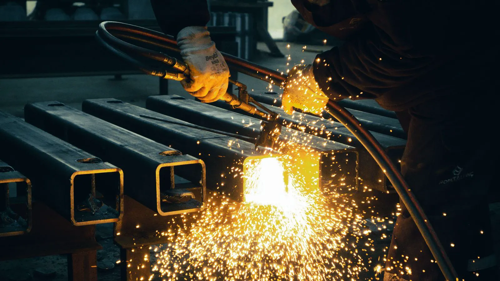
Specify weld penetration depth in sheet metal RFQs by defining material thickness, joint type, and acceptance criteria. Use standard terminology, reference applicable codes, and include visual references. This approach prevents ambiguity and ensures vendors can produce reliable sheet metal welding results.
- Define penetration depth using measurable dimensions rather than vague terms like "through".
- Match weld specifications to the joint geometry and material thickness of the sheet metal parts.
- Include acceptance criteria and inspection methods in the RFQ to verify weld quality.
Why Penetration Depth Matters in Sheet Metal RFQs
Ambiguous weld instructions cause rework and disputes. When a buyer asks for a “strong weld” without specifying penetration depth, the vendor may interpret the requirement based on cost, speed, or convenience. This leads to inconsistent results across batches and potential failures in service.
Sheet metal welding requires precise specifications because thin materials respond differently to heat input than structural steel. A joint that meets requirements for 6 mm plate may fail on 1 mm sheet if the same heat settings apply. The RFQ must translate engineering intent into measurable parameters that a fabrication shop can execute consistently.
Consider a thin-walled enclosure with 1.2 mm stainless steel panels welded into a box shape. If the RFQ only says “weld all seams,” one shop might use a low-heat TIG pass to prevent burn-through, producing a shallow bead. Another shop might use a higher-amperage MIG pass, risking distortion or a porous weld. The buyer receives two different parts that look identical on the surface but have different internal structures. Only a stated penetration depth, such as “minimum 1.0 mm penetration on both sides,” closes this gap.
What Are the Prerequisites for Specifying Penetration Depth
Before writing the RFQ, confirm three items.
First, identify the material and thickness. Specify the alloy, such as mild steel, stainless steel, or aluminum, and the gauge or thickness in millimeters. Do not assume the vendor will infer material from the drawing. For example, 10-gauge steel and 10-gauge aluminum have different conductivities and melting points. The same amperage setting will heat aluminum much faster than steel. If the material is unspecified, the vendor may default to steel settings, resulting in burn-through on aluminum or inadequate fusion on steel.
Second, define the joint type. A butt joint, lap joint, or T-joint requires different penetration approaches. A lap joint of 1 mm sheets may need a full penetration weld on both sides, while a T-joint might only require penetration into the flange. In a lap joint, the weld pool flows across two surfaces. If the penetration does not reach the root of the overlap, stress concentrates at the edge, causing fatigue cracks under vibration.
Third, determine the service condition. If the joint must withstand cyclic loading, vibration, or pressure, the penetration requirement increases. A static bracket may tolerate a shallower weld than a pressure vessel flange. A pump housing exposed to thermal cycling requires a weld that resists cracking. A decorative panel with no load may only need a shallow weld for appearance. The service condition dictates whether the weld is a structural element or a cosmetic feature.
Step-by-Step Guide to Writing the Weld Specification
Follow these steps to create a clear technical requirement.
-
State the material and thickness explicitly.
Reason: Thickness determines the required heat input and penetration depth. A 2 mm sheet needs less penetration than a 10 mm plate, and material type affects weld metal selection. For instance, specify “AISI 304 stainless steel, 1.5 mm thickness” rather than just “stainless steel.” This tells the vendor to select a matching filler rod, such as ER308L, and to adjust the amperage to prevent heat-affected zone sensitization. -
Describe the joint geometry.
Reason: The angle and overlap of the joint affect how the weld pool flows. A V-groove joint requires different preparation than a square butt joint. Include a sketch or cross-section if the geometry is non-standard. For a V-groove, specify the included angle, such as 60 degrees, and the root gap. This ensures the welder knows how much filler metal to deposit and how to maintain the arc angle. -
Specify the penetration depth in millimeters.
Reason: Use absolute measurements rather than percentages. A requirement of “3 mm penetration” is clearer than “full penetration” when the material thickness is 4 mm. If full penetration is required, state “100% penetration through the joint” and define the minimum depth. For a 3 mm sheet, specify “minimum 2.5 mm penetration on each side.” This allows for slight variation in cutting thickness but ensures adequate fusion. -
Reference the applicable welding code or standard.
Reason: Codes provide definitions for terms like “full penetration” and “partial penetration.” Referencing a standard removes ambiguity and aligns expectations between the buyer and vendor. Citing a recognized code, such as a national or international welding standard, gives both parties a shared language for defect acceptance and weld preparation. -
Define the weld size and profile.
Reason: Penetration depth and weld leg size are related but distinct. Specify the leg length for fillet welds or the reinforcement height for butt welds. This ensures the weld has adequate cross-sectional area. For a fillet weld on a T-joint, specify a leg size of 3 mm. This defines the triangular cross-section of the weld and its volume, which affects load-bearing capacity. -
Include inspection and acceptance criteria.
Reason: Without inspection requirements, the vendor may assume visual inspection is sufficient. Specify whether the weld requires dye penetrant, X-ray, or ultrasonic testing. Define the acceptance criteria for each method. For example, state “visual inspection with no cracks, porosity larger than 1 mm, or undercut.” If radiographic testing is required, specify the acceptance level, such as “no cracks or incomplete fusion visible in the radiograph.” -
Provide visual references or examples.
Reason: Words can be interpreted differently. A cross-section drawing or a photo of an acceptable weld sample removes doubt. Use these references as supplementary tools, not as the sole specification. A photo of a smooth, uniform bead with no spatter helps the vendor understand the expected finish. A cross-section drawing shows the intended fusion zone and root profile. -
Clarify preheat and post-weld requirements.
Reason: Preheat reduces cracking risk in thicker or high-strength materials. Post-weld stress relief may be required for certain alloys. State these conditions if they apply to the joint. For high-strength steel, specify a preheat temperature range, such as 100 to 150 degrees Celsius. For stainless steel, specify no preheat to minimize sensitization. -
Specify the welder qualification and process.
Reason: A certified welder using a qualified procedure produces consistent results. Reference the process, such as MIG or TIG, and require welder qualification per the applicable code. For a critical bracket, specify “TIG welding by a certified welder per the applicable code.” This ensures the operator has the skill to control the arc and filler metal deposition.
How to Handle Different Joint Types
Different joints require different penetration strategies. The following table shows common scenarios and recommended specifications.
| Joint Type | Material Thickness | Recommended Specification |
|---|---|---|
| Butt joint | 1-3 mm | Full penetration, both sides if accessible |
| Lap joint | 1-2 mm | Full penetration on both sides, 100% coverage |
| T-joint | 2-4 mm | Penetration into flange, minimum 1 mm |
| Corner joint | 1-3 mm | Full penetration or fillet weld with specified leg size |
| Overlapping flange | 3-6 mm | Partial penetration, 50-75% of thickness |
For lap joints in thin sheet, full penetration on both sides is often required to prevent stress concentration at the weld toe. A 1 mm lap joint with a 3 mm overlap should have a continuous bead on both faces. If the overlap is larger, such as 5 mm, consider a partial penetration weld on the front side and a full penetration weld on the back side to balance heat input and strength.
For T-joints, ensure the penetration reaches the root of the joint to avoid cracking under load. A T-joint connecting a 2 mm flange to a 4 mm plate should have a fillet weld with a 3 mm leg on both sides. The penetration should reach at least 50% of the flange thickness to ensure a strong connection.
Common Mistakes in RFQ Weld Specifications
Buyers frequently make errors that lead to rework or disputes.
Using vague terms. Phrases like “strong weld” or “full penetration” without dimensions create ambiguity. “Full penetration” means different things in different contexts. Always define the depth in millimeters. For example, “full penetration” for a 2 mm sheet means 2 mm depth, but for a 10 mm plate, it means 10 mm. Specify “minimum 2.0 mm penetration” for the thin sheet to be clear.
Ignoring joint access. If the joint is in a confined space, full penetration may be impossible. Specify which sides are accessible and what penetration is achievable. For a box-shaped enclosure with a closed corner, full penetration on the inside may be impossible. Specify “single-side penetration, minimum 1.5 mm, on the accessible side.”
Mismatched material and process. Specifying a process without considering material thickness leads to poor results. For example, TIG welding 8 mm steel is labor-intensive and may not be economical. MIG welding may be more practical for thicker sections. For thin sheet, TIG provides better control, while MIG is faster for production runs. Match the process to the thickness and volume.
No inspection criteria. Without defined inspection methods, the buyer cannot verify compliance. Specify whether visual, dye penetrant, or radiographic testing is required. For a non-critical enclosure, visual inspection may be sufficient. For a pressure-containing joint, radiographic testing is required. State the method and acceptance criteria in the RFQ.
Lack of visual references. A simple sketch or photo of an acceptable weld prevents misinterpretation. Use these as supporting documents. A photo of a smooth, even bead with no spatter or porosity helps the vendor understand the expected quality. A cross-section drawing shows the intended fusion zone and root profile.
Verification Step: How to Confirm the Specification
Before releasing the RFQ, run a verification check.
- Read the specification aloud. If any sentence could be interpreted two ways, rewrite it. For example, “weld the seam” is vague. Change it to “apply a continuous TIG weld with 1.5 mm penetration on both sides.”
- Cross-check the penetration depth against the material thickness. Ensure the requirement is physically achievable. A 4 mm penetration requirement on a 2 mm sheet is impossible. Adjust the depth to match the thickness.
- Confirm the joint geometry matches the drawing. A 3 mm penetration requirement on a 2 mm sheet is impossible. Verify the thickness and geometry are consistent.
- Verify that the inspection method is appropriate for the joint. Dye penetrant may be sufficient for surface defects, but X-ray is needed for internal flaws. For a butt joint in a pressure vessel, X-ray is required. For a surface-mounted bracket, dye penetrant may be sufficient.
- Ask a welder to review the specification. A practical check catches gaps that engineers miss. A welder can identify if the access is limited or if the penetration depth is too aggressive for the material.
If the specification passes this check, release it to the vendor. Include a revision history if changes are made. Clear specifications reduce communication errors and align expectations from the start.
When to Involve a Welding Engineer
Some RFQs require specialized input. If the joint is safety-critical, subject to high pressure, or involves dissimilar materials, engage a welding engineer. They can define the procedure, select the correct filler metal, and set the inspection thresholds.
For a bridge component or an aircraft structure, a welding engineer is necessary. They can analyze the stress concentrations and define the exact penetration depth and inspection requirements. For a dissimilar material joint, such as steel to aluminum, a welding engineer can specify the correct filler metal and process to prevent galvanic corrosion or cracking.
For standard production brackets or enclosures, the steps above are sufficient. For critical assemblies, add a weld procedure specification as an attachment to the RFQ. This document details the heat input, travel speed, and filler metal used. It ensures the vendor uses a proven method that produces consistent results.
Final Checklist for RFQ Weld Specifications
Use this checklist before submitting the RFQ.
- Material and thickness specified
- Joint type and geometry defined
- Penetration depth in millimeters stated
- Applicable welding code referenced
- Weld size and profile described
- Inspection method and acceptance criteria defined
- Visual reference included
- Preheat and post-weld requirements stated
- Welder qualification and process specified
A well-written RFQ saves time and money. It reduces the number of clarification questions and minimizes the risk of receiving a weld that does not meet the intended strength. The goal is not to over-specify, but to specify with precision.
Frequently asked questions
What is the difference between full and partial penetration in sheet metal welding?
Full penetration means the weld metal reaches the root of the joint on all sides. Partial penetration means the weld only reaches a specified depth, such as 50% of the material thickness.
How do I determine the correct penetration depth for my sheet metal part?
Determine the penetration depth based on the material thickness, joint type, and service conditions. For critical applications, consult a welding engineer or applicable code.
Can I use a photo as a specification for weld penetration?
A photo can support the specification but should not replace it. Use a photo as a visual reference alongside written dimensions and code references.
What inspection method is best for sheet metal welds?
The best method depends on the joint and application. Visual inspection is basic, dye penetrant finds surface defects, and X-ray or ultrasonic testing detects internal flaws. Specify the method based on the risk.
Do I need to specify the welding process in the RFQ?
Yes. Specify the process, such as MIG or TIG, and reference the applicable code. This ensures the vendor uses a suitable method for the material and thickness.