DfM laser vs brake rules differ because cutting and bending create distinct part geometries. Laser design focuses on kerf, tooling, and nesting. Brake design focuses on bend radius, tonnage, and flange height. Both require material-specific limits.
- Laser DfM prioritizes tooling, kerf compensation, and nest efficiency over bend features.
- Brake DfM prioritizes bend angles, flange heights, and material tonnage over cut dimensions.
- Sharp internal corners cause tooling and bending issues that require specific allowances.
- Combining both processes requires shared design checks to prevent clashes.
- Material thickness and alloy determine whether a part needs a different DfM approach.
Where laser and brake DfM rules differ
Laser cutting and CNC bending solve different problems in sheet metal fabrication. Laser DfM controls the perimeter of the part. It sets how the tool enters and exits the material, how much metal is removed, and how multiple pieces fit on a sheet. Brake DfM controls the geometry after the part is cut. It sets how the metal folds, how much material is consumed in each bend, and how the final part holds its shape.
A common mistake is applying the same design rules to both processes. Engineers often focus on flat patterns and ignore how the laser tool path interacts with sharp corners. They also ignore how the press brake tooling limits the minimum flange height. The result is a part that looks correct on the CAD model but fails during fabrication.
Laser cutting and CNC bending are not interchangeable. They require different checks, different allowances, and different documentation in an RFQ. This section compares the two approaches so you can apply the correct rules to each part.
What laser cutting design requires
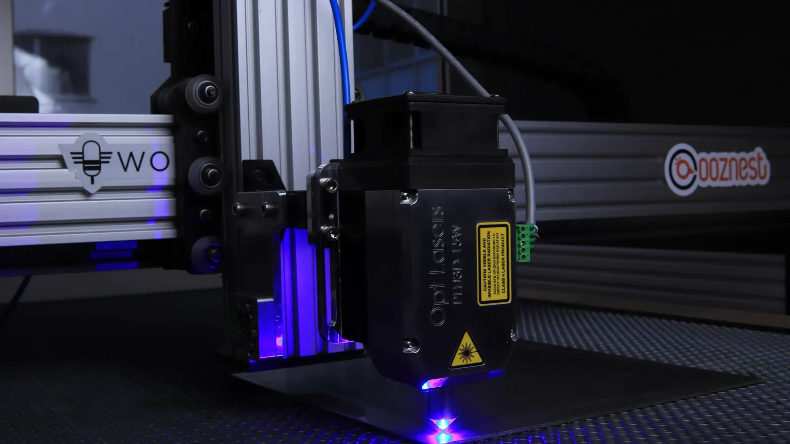
Laser cutting design focuses on the tool path and the material it leaves behind. The laser beam removes a small amount of metal, known as the kerf. Every internal cut consumes this width. The laser also creates a small heat affected zone on the edges. The size of these zones depends on the material and the laser power.
The most critical laser DfM rule is the tool path. The laser must have a clear entry and exit point. A closed loop without a break causes the tool to start in the middle of the cut. This creates a small hole or a rough start point. Designers must include a small break in the loop, often called a tooling break or a relief cut.
Internal features also require attention. Small holes and narrow slots are difficult for the laser to cut cleanly. The tool needs enough room to accelerate and decelerate. If a hole is too small, the laser may not cut through the material completely. If a slot is too narrow, the heat from the cut may damage the surrounding metal.
Nesting efficiency is another major factor. Laser cutting costs are often tied to the number of cuts and the time the laser spends on the sheet. A design that packs parts tightly on the sheet reduces material waste and machine time. A design with many small parts and large gaps wastes material and increases cost. Designers should review the flat pattern and consider how the parts can be grouped.
What CNC bending design requires
CNC bending design focuses on the fold. The press brake uses a die and a punch to bend the metal. The punch pushes the metal into the die. The bend radius is set by the die width. The bend angle is set by the punch stroke. The tonnage required depends on the material thickness and the alloy.
The most critical brake DfM rule is the minimum bend radius. A sharp 90 degree corner is not possible in a press brake. The metal must have a finite radius. The smaller the radius, the more force is required. If the radius is too small for the die, the part will not bend. If it is too small for the material, the metal may crack. Designers must specify the bend radius or accept a standard minimum for the material.
Flange height is the second major constraint. The flange is the straight portion of the metal that extends from the bend. The press brake can only bend a certain amount of metal before the punch reaches the die. If the flange is too short, the bend will not form correctly. Designers must check the flange height against the material thickness and the bend angle.
The order of operations matters too. Some parts require bending before cutting. Others require cutting before bending. If the part is bent first, the laser cannot cut a curved edge easily. If the part is cut first, the bend lines must be located on the flat pattern. Designers must define the sequence in the drawing.
Comparison: DfM laser vs brake rules
The table below compares the primary design rules for each process.
| Option | Best for | Limitations |
|---|---|---|
| Laser cutting | Complex perimeters, small features, high volume parts | Tooling breaks, kerf width, heat affected zone |
| CNC bending | 90 degree bends, multi-flange parts, structural frames | Minimum bend radius, flange height, tonnage limits |
| Combined laser and brake | Most sheet metal enclosures and brackets | Requires shared flat pattern, sequence of operations |
Laser cutting is best for parts with intricate outlines. The laser can cut complex curves, small holes, and detailed features that are difficult to form by hand. It is also well suited for high volume production because the tool path can be automated. The limitation is that the laser cannot create a bend. It only removes material. The resulting part is flat.
CNC bending is best for parts that need to hold a shape. The press brake can create consistent 90 degree bends and other angles. It is well suited for enclosures, brackets, and frames. The limitation is that the press brake cannot cut complex perimeters. It requires a flat pattern with straight edges and defined bend lines.
The combined approach is the most common for sheet metal parts. The laser cuts the flat pattern. The press brake folds it. This requires coordination between the two processes. The flat pattern must account for the bend deductions. The laser must cut the part with the correct dimensions after bending.
When to pick laser first
Pick laser first when the part has complex geometry that cannot be formed by hand. This includes parts with many small holes, intricate cutouts, or curved edges. The laser can cut these features accurately. The design must include tooling breaks for the laser tool path. Internal holes must be large enough for the tool to cut through.
Laser first is also preferred when the part requires high volume production. The laser can cut many parts on a single sheet. The nesting software optimizes the layout to reduce material waste. The flat pattern is then fed to the press brake. The bend lines must be clearly marked on the flat pattern.
The limitation of laser first is that the part is flat after cutting. The press brake must be available to form the bends. If the part has many bends, the tonnage required may be high. Designers must check the material thickness and the alloy to ensure the press can handle the job.
When to pick brake first
Pick brake first when the part is a simple shape that can be formed by hand. This includes parts with a single bend or a few 90 degree folds. The press brake can form these bends quickly. The design must specify the bend radius and the flange height.
Brake first is also preferred when the part is large and the bending tonnage is low. Large parts are difficult to cut with a laser if the sheet size is limited. The press brake can form the part first. Then the laser can cut the edges. This reduces the size of the part that needs to be cut.
The limitation of brake first is that the part must be flat before cutting. If the part has complex geometry, the laser cannot cut the curved edges easily. The design must account for the bend deductions. The flat pattern must be calculated correctly to ensure the final dimensions are accurate.
Shared checks for both processes
Both laser and brake designs require the same basic checks. The material must be specified with the alloy and the thickness. The bend radius must be defined for the brake. The tooling break must be defined for the laser. The flat pattern must be calculated correctly.
The order of operations must be clear. The drawing must state whether the laser cuts before or after the brake. The bend lines must be located on the flat pattern. The tooling breaks must be marked on the cut lines. The final dimensions must be checked against the flat pattern.
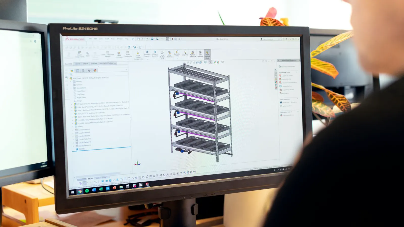
A common mistake is to design the part in 3D and ignore the flat pattern. The 3D model shows the final shape. The flat pattern shows how the part is made. The two must match. If they do not, the part will not fit. Designers must review the flat pattern and check the dimensions.
How to document DfM in an RFQ
An RFQ should specify the DfM rules for each process. The laser section should state the material, the thickness, and the tooling requirements. The brake section should state the bend radius, the flange height, and the tonnage. The drawing should include the flat pattern and the bend lines.
The RFQ should also state the edge finish. The laser cut edge is usually smooth. The brake bend edge may have a burr. The design should specify whether the edge needs to be deburred. The edge finish affects the final appearance and the fit of the part.
A clear RFQ reduces errors. The fabrication shop can review the design and flag any issues before cutting the metal. The cost of a change after cutting is much higher than the cost of a change before cutting.
Frequently asked questions
What is the main difference between laser and brake DfM rules?
Laser DfM controls the cut path and kerf width. Brake DfM controls the bend radius and flange height. They apply to different stages of the part.
Can a part be cut by laser and bent by brake?
Yes. Most sheet metal parts are cut by laser and bent by brake. The flat pattern must account for both processes.
What is a tooling break?
A tooling break is a small break in a closed loop that allows the laser tool to enter and exit the cut. It prevents a hole at the start point.
What is the minimum bend radius?
The minimum bend radius is the smallest radius the press brake can create without cracking the metal. It depends on the material and the thickness.
How do I check the flat pattern?
Check the flat pattern against the 3D model. Ensure the bend deductions are correct. Verify the final dimensions match the drawing.