This article provides a practical, step-by-step verification checklist for sheet metal dimensional tolerances. It helps importers and buyers confirm parts meet specifications through structured quality control.
- Verify all critical dimensions against the drawing before acceptance.
- Check for warpage, bend allowance, and hole alignment as common failure points.
- Confirm measurement methods match the drawing’s specified tolerance class.
- Document deviations clearly to support corrective actions.
- Use a structured checklist to ensure consistency across inspections.
Introduction
Sheet metal fabrication requires precision to ensure parts function correctly in assembly and manufacturing. Importers and buyers often face challenges when verifying that received parts meet the specified dimensions before production. A structured checklist provides a clear path to confirm compliance and reduce the risk of costly rework or rejection.
This guide offers a practical, step-by-step verification checklist for checking sheet metal dimensional tolerances. It is designed for quality control teams, engineers, and buyers who need a reliable method to audit parts on arrival.
What Are Dimensional Tolerances in Sheet Metal?
Dimensional tolerances define the acceptable range of variation for a part’s dimensions. In sheet metal, these include overall length, width, thickness, bend angles, hole positions, and flatness. Tolerances are specified on the engineering drawing and must be verified using appropriate measurement tools.
Common tolerances may be expressed as plus-minus values, such as ±0.5 mm, or as a single-sided deviation. The drawing may also specify a tolerance class based on industry standards, such as ISO or ASME, depending on the project requirements.
Section 1: Pre-Inspection Preparation
Before measuring any part, ensure the inspection environment and tools are ready.
- Review the drawing and specifications. Confirm that the drawing revision is current and that all critical dimensions are identified. Check for any special notes regarding tolerance classes or inspection methods.
- Select the correct measurement tools. Use calipers, micrometers, gauges, or CMMs based on the required precision. For example, a digital caliper is suitable for general dimensions, while a micrometer is better for thickness or tight tolerances.
- Calibrate your tools. Verify that your instruments are within calibration dates. Outdated or uncalibrated tools can lead to false readings.
- Prepare a clean inspection area. Dust, debris, or surface contamination can affect measurement accuracy. Wipe parts and tools before starting.
- Define the acceptance criteria. Clearly state which dimensions are critical, which are nominal, and what deviation triggers rejection or rework.
Section 2: Verifying Overall Dimensions
Overall dimensions are the first point of focus during inspection.
- Measure length and width. Use calibrated calipers to measure the part’s overall length and width at multiple points. Check for consistency and deviation from the drawing.
- Check thickness. Measure the material thickness at several locations. Sheet metal thickness can vary due to rolling, forming, or cutting.
- Inspect for warpage or flatness. Place the part on a flat reference surface. Use a straightedge or a surface plate to check for bowing, twist, or unevenness. Warpage can affect assembly and function.
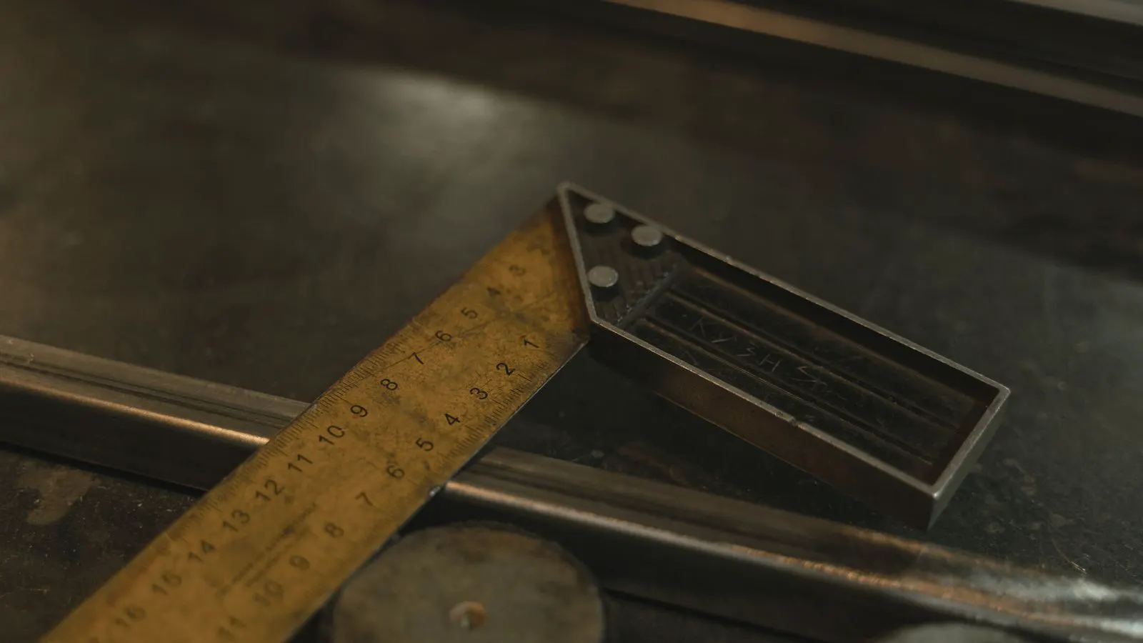
- Verify bend angles. Use a protractor or angle gauge to confirm that bends are within the specified tolerance. Bend angles are critical for parts that must align with other components.
Section 3: Checking Hole and Feature Locations
Hole positions and features are often critical for assembly.
- Measure hole spacing. Verify the distance between holes matches the drawing. Use calipers or a pin gauge to confirm alignment.
- Check hole diameter. Use a pin gauge or bore gauge to ensure hole sizes are within tolerance. Holes that are too small or too large can cause fit issues.
- Inspect edge quality. Look for burrs, chips, or deformation around holes. Poor edge quality can indicate a problem with the punching or laser cutting process.
- Verify slot and notch dimensions. If the part includes slots or notches, measure their length, width, and position. These features are often critical for alignment.
Section 4: Assessing Surface and Finish Quality
Surface quality can affect both function and appearance.
- Check for scratches or dents. Inspect the part for visible damage that may indicate handling errors or manufacturing defects.
- Verify coating or finish thickness. If the part has a coating, such as zinc plating or powder coat, measure the thickness to ensure it meets specifications.
- Inspect for weld defects. If the part includes welds, check for porosity, cracks, or uneven penetration.
- Confirm deburring. Ensure that all burrs and sharp edges are removed. Burrs can cause injury and interfere with assembly.
Section 5: Documentation and Reporting
Accurate documentation is essential for quality control and traceability.
- Record all measurements. Log each measured value, including the tool used and the date of inspection.
- Flag deviations. Clearly mark any dimensions that fall outside the specified tolerance. Note whether the deviation is acceptable for the application or requires rework.
- Attach photos. Include photographs of any defects or areas of concern. This helps communicate issues to the manufacturer or supplier.
- Issue a disposition. Assign a status to each part: accept, reject, or rework. This decision should be based on the inspection findings and the drawing requirements.
- Share reports with stakeholders. Provide the inspection report to the buyer, engineer, or production team. Clear communication helps prevent future issues.
Section 6: Common Red Flags and How to Address Them
| Red Flag | Possible Cause | Action |
|---|---|---|
| Consistent deviation in one dimension | Tool calibration error or manufacturing drift | Recalibrate tools; request a process adjustment from the supplier |
| Warpage or bowing | Improper heat treatment or uneven cooling | Reject or rework; request a process improvement |
| Holes slightly out of position | Poor fixture alignment or tool wear | Verify fixture setup; request replacement of worn tools |
| Surface scratches or dents | Handling or packaging damage | Inspect packaging; request better handling procedures |
| Coating thickness out of spec | Inconsistent coating application | Reject or rework; request a coating process review |
Section 7: Best Practices for Ongoing Verification
- Use a standardized checklist. A consistent checklist ensures that all parts are inspected the same way, reducing variability.
- Train inspection staff. Ensure that inspectors understand how to use measurement tools and interpret tolerance specifications.
- Conduct periodic audits. Review inspection records regularly to identify trends or recurring issues.
- Maintain a feedback loop. Share inspection results with the manufacturer to improve future production.
- Update the checklist as needed. As designs change or new standards are adopted, update the checklist to reflect current requirements.
Conclusion
Verifying sheet metal dimensional tolerances is a critical part of quality control. By following a structured checklist, importers and buyers can ensure that parts meet specifications and reduce the risk of assembly failures. This guide provides a practical framework for inspection, from pre-check preparation to final documentation. Use this checklist as a reference and adapt it to your specific project needs.
Frequently asked questions
What are the most common dimensions to verify in sheet metal parts?
The most common dimensions to verify include overall length, width, thickness, bend angles, hole positions, and flatness. These dimensions are critical for assembly and function.
How often should I calibrate my measurement tools?
Measurement tools should be calibrated at least once a year, or more frequently if they are used heavily or if you notice inconsistencies in readings. Always follow your company’s calibration schedule.
What if a part has a deviation that is within tolerance but still causes fit issues?
If a part is within tolerance but causes fit issues, it may be a design or assembly problem. Contact the engineer to review the drawing and determine if a design change is needed.
Can I use a standard caliper to measure all dimensions?
A standard caliper is suitable for general dimensions, but for tight tolerances or thickness measurements, you may need a micrometer or a CMM. Always use the appropriate tool for the required precision.
How do I document deviations in a way that is useful for the supplier?
Document deviations by including the measured value, the specified tolerance, the tool used, and a photograph of the defect. Clearly state the disposition (accept, reject, or rework) and attach the report to the inspection records.